What Is PCB Manufacturing and Assembly?

PCB manufacturing and assembly transforms an electronic design into a working, testable circuit board. The process begins with copper-clad materials, carefully patterned traces, drilled holes, and protective surface finishes. Assembly then places components onto the board, often using automated pick-and-place equipment and controlled soldering profiles. Small details matter. A misplaced resistor can stop an entire product from operating.

This article explains how pcb manufacturing and assembly works in practical terms. It covers design preparation, material selection, fabrication, component placement, soldering, inspection, and functional testing. Experienced manufacturers typically review Gerber files, drill data, bills of materials, and assembly drawings before production. They also check spacing, pad dimensions, component availability, and thermal requirements. These reviews reduce preventable defects, but they cannot replace careful engineering judgment.

Quality depends on more than advanced machinery. It also relies on traceable materials, trained operators, calibrated inspection systems, and documented process controls. Standards such as IPC guidelines can support consistent workmanship, although requirements may vary by product and application. Some designs still fail after passing visual inspection. Hidden solder joints, marginal tolerances, or incomplete test coverage can reveal weaknesses later. That possibility deserves attention.

A reliable manufacturing partner communicates clearly about yield, lead times, risks, and revisions. Prototype boards may expose problems that looked invisible on a screen. Those lessons can improve the next design. Understanding each production stage helps engineers, buyers, and product teams make better decisions before volume manufacturing begins.
What Is PCB Manufacturing and Assembly?

PCB Manufacturing and Assembly: Core Concepts and Differences

What Is PCB Manufacturing and Assembly?

PCB Manufacturing and Assembly: Core Concepts and Differences

PCB manufacturing creates bare circuit boards from laminate, copper foil, and protective coatings. The process includes circuit imaging, etching, drilling, plating, solder mask application, and surface finishing. Each stage affects electrical performance and mechanical reliability. A tiny drill offset can weaken a via or reduce soldering space. Manufacturing focuses on the board itself, before components are installed. Engineers inspect line width, hole size, copper thickness, and insulation spacing against controlled specifications. Small deviations matter.

PCB assembly populates the finished board with electronic components. Machines place resistors, capacitors, integrated circuits, and connectors onto prepared pads. Reflow soldering melts solder paste under a controlled thermal profile. Through-hole parts may require selective or wave soldering. Inspection systems check polarity, placement, solder joints, and component height. Assembly concerns the complete functional unit, not only the layered substrate. It may also include programming, electrical testing, and mechanical inspection.

The difference is practical: manufacturing builds the platform, while assembly equips it to operate. A flawless bare board cannot function alone. Accurate component placement cannot repair damaged traces or poor plating. The boundary is not always clean. Some facilities perform electrical tests during manufacturing, while others handle them during assembly. A common production lesson is that visual quality can mislead. A clean-looking board may still contain hidden voids, weak vias, or intermittent connections. Careful inspection remains essential.

Preparing a PCB Design for Reliable Production

What Is PCB Manufacturing and Assembly?

Preparing a PCB Design for Reliable Production

A reliable PCB begins with manufacturing limits, not only with a clean schematic. Before releasing files, check the layer stack, copper thickness, trace width, spacing, and minimum drill size. These details affect heat, signal quality, and fabrication yield. A narrow trace may work in simulation but fail during etching or rework.

Use clear footprints with verified pad dimensions and accurate component outlines. Confirm pin one markings, polarity symbols, and courtyard spacing. Leave enough room around connectors for inspection and assembly tools. Add test points where technicians can reach them without removing nearby parts. Small labels matter. A silkscreen reference hidden under a component can slow troubleshooting.

I review the design against the fabricator’s current design rules, then inspect the exported files separately. Gerber or equivalent manufacturing layers, drill data, pick-and-place files, and assembly drawings must agree. Check for missing solder mask openings, accidental copper islands, and incomplete thermal reliefs. Panelization also deserves attention, especially near board edges and breakaway tabs.

I still find errors after careful reviews. That is normal, but it should change the process. A prototype can reveal uneven solder joints, insufficient clearance, or heat buildup near a regulator. Record those findings and update the design rules. Reliable production comes from measurable checks, practical prototypes, and honest attention to small details.

The Main Stages of PCB Fabrication

What Is PCB Manufacturing and Assembly?

The Main Stages of PCB Fabrication

A PCB begins with a reviewed circuit design and precise manufacturing files. Engineers check layer alignment, trace widths, hole sizes, and clearance distances. Small errors matter. Copper-clad laminate is then cut into panels and cleaned carefully. Dust or oil can weaken later bonding. Inner-layer patterns are transferred onto copper using imaging equipment. Unwanted copper is etched away, leaving the required electrical paths.

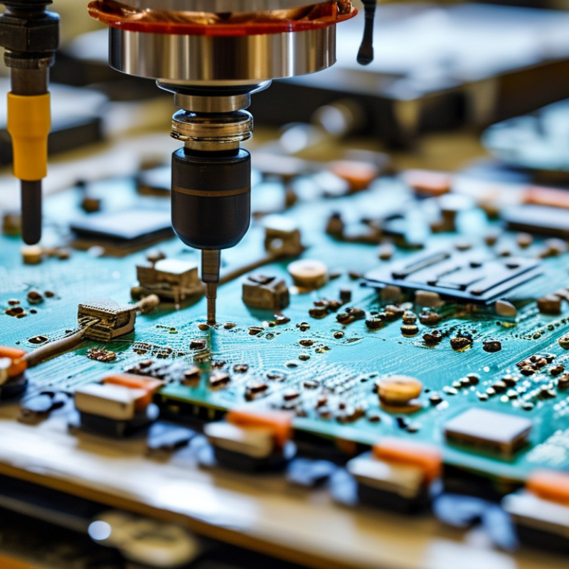
The panels are pressed together with insulating material and copper foil. Drilling creates holes for component leads and connections between layers. These holes are cleaned before chemical plating adds conductive copper inside them. Outer-layer imaging and etching shape the remaining circuit pattern. A solder mask covers most copper surfaces and leaves selected pads exposed. Text markings are applied afterward. The surface finish must remain even, or solder may spread poorly.

Fabrication is not complete until inspectors verify dimensions, layer registration, and electrical continuity. Automated optical inspection can find missing traces, excess copper, and small scratches. Electrical testing checks for open circuits and unwanted shorts. After fabrication, assembly begins with solder paste, component placement, and controlled heating. Operators inspect joints for bridges, weak wetting, or shifted parts. A clean result is not guaranteed. Poor temperature control can ruin an otherwise accurate board. Careful records and repeated checks make the process more reliable.

What Is PCB Manufacturing and Assembly? - The Main Stages of PCB Fabrication

Main Stage Purpose Typical Activities Primary Output Important Quality Considerations
1. Design and Engineering Convert an electrical circuit into a manufacturable printed circuit board design.
  • Create the schematic and assign component footprints.
  • Develop the PCB layout, including traces, copper areas, vias, and mounting holes.
  • Define the layer stack-up, board thickness, materials, and design rules.
  • Generate manufacturing data such as Gerber files and drill files.
Validated design files and manufacturing documentation.
  • Correct electrical connections
  • Suitable trace width and spacing
  • Clear component placement and polarity markings
  • Design-for-manufacturing compatibility
2. Material Preparation Prepare the insulating and conductive materials used to build the board.
  • Select the laminate, commonly a glass-fiber-reinforced epoxy material.
  • Prepare copper-clad panels, prepreg sheets, and copper foil.
  • Cut panels to production size and clean their surfaces.
Clean, correctly sized panels ready for imaging and layer formation.
  • Material thickness and copper weight
  • Surface cleanliness
  • Moisture control
  • Correct material specification
3. Inner-Layer Imaging Transfer the inner copper circuit pattern onto the copper surface.
  • Apply a photosensitive dry film to the copper panel.
  • Expose the film using the circuit image.
  • Develop the panel to reveal the areas that will form the circuit.
Inner-layer panels with the required circuit pattern defined.
  • Accurate image registration
  • Consistent film adhesion
  • Correct exposure and development
  • No pinholes or unwanted pattern loss
4. Inner-Layer Etching Remove unwanted copper and leave the designed conductive traces.
  • Etch exposed copper from the panel.
  • Strip the remaining photoresist.
  • Inspect the resulting traces and copper features.
Completed inner-layer circuitry.
  • Controlled trace width
  • Absence of shorts and opens
  • Proper copper adhesion
  • Accurate circuit geometry
5. Layer Alignment and Lamination Combine multiple circuit layers into a single rigid multilayer board.
  • Align inner layers, prepreg, and copper foil using registration targets.
  • Stack the materials in the specified order.
  • Apply controlled heat and pressure in a lamination press.
A bonded multilayer panel with embedded copper layers.
  • Layer-to-layer registration
  • Uniform resin flow
  • Strong bonding between layers
  • Control of voids and delamination
6. Drilling Create holes for vias, component leads, mounting hardware, and other mechanical features.
  • Drill plated and non-plated holes according to the drill file.
  • Use mechanical drilling or laser drilling when appropriate.
  • Remove drilling debris and prepare hole walls for plating.
Panel with accurately located holes and vias.
  • Hole diameter and position
  • Clean hole walls
  • Minimal burrs and smear
  • Correct distinction between plated and non-plated holes
7. Through-Hole Plating Create electrical connections between copper layers through drilled holes.
  • Clean and condition the drilled holes.
  • Deposit a thin conductive layer on the hole walls.
  • Build the copper thickness through electroplating.
Electrically connected plated holes and reinforced outer copper.
  • Continuous copper coverage inside holes
  • Uniform plating thickness
  • Reliable interlayer connectivity
  • No voids or cracks in hole barrels
8. Outer-Layer Pattern Formation Define the final copper traces, pads, and other conductive features on the outer layers.
  • Apply photoresist and transfer the outer-layer image.
  • Electroplate exposed copper features.
  • Strip the resist and etch away unwanted copper.
Outer-layer circuitry with pads, traces, and plated connections.
  • Accurate conductor dimensions
  • Correct pad geometry
  • No bridging between adjacent conductors
  • Reliable plated-through connections
9. Solder Mask Application Protect selected copper areas and reduce the risk of solder bridges during assembly.
  • Apply a liquid photosensitive solder mask.
  • Expose and develop the mask to keep solderable pads open.
  • Cure the mask using controlled heat or ultraviolet energy.
Board with protected copper and exposed soldering pads.
  • Proper pad clearance
  • Uniform coverage and color
  • Strong adhesion
  • No mask contamination on solderable surfaces
10. Surface Finish Protect exposed copper pads from oxidation and improve solderability.
  • Apply a specified finish, such as hot air solder leveling, electroless nickel immersion gold, immersion tin, or organic surface preservative.
  • Control the finish thickness and surface uniformity.
Protected, solderable component pads and contact surfaces.
  • Finish thickness
  • Surface flatness
  • Oxidation resistance
  • Compatibility with the assembly process
11. Marking, Routing, and Electrical Testing Add identification details, separate individual boards, and verify circuit integrity.
  • Print component references, polarity symbols, warnings, and revision information.
  • Route or score the production panel into individual boards.
  • Perform automated optical inspection and electrical tests for opens and shorts.
Separated and tested bare PCBs ready for component assembly.
  • Legible markings
  • Accurate board dimensions
  • Correct edge profile
  • Verified electrical continuity and isolation
12. PCB Assembly Mount and solder electronic components onto the fabricated bare board.
  • Apply solder paste through a stencil for surface-mount components.
  • Place components using automated or manual placement equipment.
  • Reflow the solder to form permanent joints.
  • Insert and solder through-hole components when required.
Populated printed circuit board assembly.
  • Component orientation and placement accuracy
  • Correct solder volume
  • Reliable solder joints
  • Protection against electrostatic discharge
13. Final Inspection and Functional Testing Confirm that the completed assembly meets design, safety, and functional requirements.
  • Inspect solder joints and component placement.
  • Use automated optical inspection, X-ray inspection, or other suitable methods.
  • Power the assembly and verify electrical functions.
  • Record test results and manage any rework.
Approved PCB assemblies with documented inspection and test results.
  • Functional performance
  • Mechanical fit
  • Absence of solder defects
  • Traceability and process documentation

How Components Are Mounted and Soldered onto a PCB

What Is PCB Manufacturing and Assembly?
How Components Are Mounted and Soldered onto a PCB

PCB assembly turns a bare circuit board into a working electronic unit. The process begins with solder paste, a gray mixture of metal particles and flux. A stainless-steel stencil places paste onto precise copper pads. Even a small offset can weaken a connection.

A pick-and-place machine positions resistors, capacitors, integrated circuits, and connectors onto the pasted board. Component orientation matters, especially for diodes, polarized capacitors, and multi-pin packages. The board then enters a reflow oven with controlled heating zones. The solder melts, flows around each lead, and forms solid joints as the board cools.

Heat must be controlled carefully. Too little heat can create dull, weak joints. Too much heat may damage sensitive components or lift copper pads. Larger parts can also absorb heat differently from tiny components, making the solder profile harder to balance. Through-hole components require another method. Their leads pass through drilled holes and are soldered from the opposite side, often using a wave or selective process.

Inspection follows soldering. Technicians check for bridges, missing parts, poor wetting, and incorrect polarity. Automated optical inspection improves consistency, but it is not flawless. A visually acceptable joint can still hide a weak mechanical connection. That is why sample testing, electrical checks, and careful process records remain important. Small errors deserve attention.

Typical Lead-Free Reflow Soldering Profile

In surface-mount PCB assembly, solder paste is printed onto the pads, components are positioned by a pick-and-place machine, and the board passes through a reflow oven. This representative profile shows preheating, soaking, reflow above the 217°C melting point of common lead-free SAC solder, peak temperature, and controlled cooling.

Inspection, Testing, and Quality Control in PCB Production

Inspection, testing, and quality control determine whether a PCB performs reliably after leaving the factory. The process starts with solder paste inspection, or SPI, which measures paste volume, height, and alignment before component placement. Automated optical inspection then checks solder bridges, missing parts, polarity, and lifted leads. X-ray inspection reveals hidden defects, including voids beneath thermal pads and poorly formed joints. Small details matter. A single misplaced resistor can stop an entire assembly.

IPC’s 2024 Global Sentiment of the Electronics Industry report surveyed more than 100 electronics manufacturers and identified supply-chain pressure, workforce shortages, and quality consistency as continuing operational concerns. These findings explain why many plants combine visual inspection with automated records and statistical process control. In practice, engineers track defect-per-million opportunities, first-pass yield, and rework rates. A rising rework rate often points to stencil wear, unstable temperature profiles, or operator fatigue. Numbers expose patterns that a clean-looking board may hide.

Electrical testing adds another layer. In-circuit testing checks component values and connections, while functional testing verifies the assembled board under realistic operating conditions. X-ray images, test logs, and lot codes should remain traceable to each production batch. IPC-A-610 and J-STD-001 provide widely used acceptance and soldering criteria, but standards cannot replace judgment. A board may pass inspection and fail later because moisture, vibration, or thermal cycling was overlooked. Quality teams should review failures honestly, including their own inspection limits. Perfect records are uncommon. Careful learning is more credible.